See the detailed specifications with the manual for our fast imaging camera.
If you have the high resoltion CCD, you need these instructions instead.
If you have the slim USB CCD, you need these instructions instead.
If you have the FLIR CMOS camera, you need these instructions instead.
If you have the Macro x-ray camera, you need these instructions instead.
If you have the 1-CCD Laue camera, you need these instructions instead.
If you have the 2-CCD Laue camera, you need these instructions instead.
If you have the EMCCD camera, you need these instructions instead.
If you have a standard video camera, you need these instructions instead.
You can download the NeutronOptics software CD for this camera.
These instructions are for Windows-10; for other versions they may be slightly different.
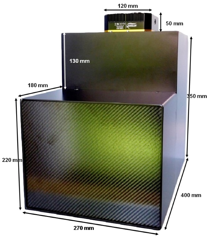
NeutronOptics Fast Imaging Camera
This camera is designed for neutron and x-ray tomography, with high efficiency, low noise and fast read-out using our high resolution VS60 CCD unit for a FOV of up to 250x200 mm. It is also suitable for imaging with fast neutrons from a D-D or D-T generator (2.45MeV or 14MeV). Fast neutrons are much harder to detect than thermal neutrons because they are not captured by nuclei to provide ionising fission fragments, so special PP/ZnS scintillators are needed to produce knock-on protons.
We use the new 1 inch Sony ICX694ALG EXview HAD CCD II to give a resolution of 2750x2200 pixels over an area of 250x200mm (90 µm resolution). Dark current is virtually eliminated by thermo-electric cooling by -35C, and high speed readout noise is low. The total noise count in 300s with the cooled CCD is only ~1c/s/pixel (~300 counts in up to 65,536), resulting in excellent dynamic range. The 180mm long front section can easily be removed to change between different neutron and x-ray scintillators. (Detailed Manual)
- Sensor: 1" Sony EXview HAD CCD II
- Optics: High resolution f/1.4 1" lens
- Resolution: 2750 x 2200 pixels
- High sensitivity: (QE~75%), low smear
- Dark current: 0.002 e/pix/s @-10 °C
- Cooling: Regulated Peltier ΔT = -35°C
- Digital Output: 16-bit 65536 levels
- Readout Time: ~1s full frame
- Binning and Region-of-Interest
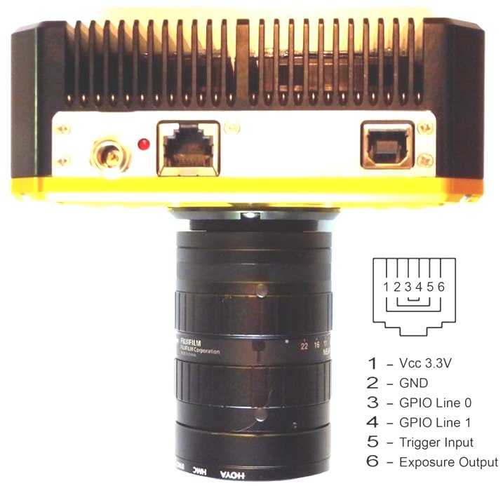
- External Trigger: GPIO synchronisation
(Click on the photos to enlarge them)
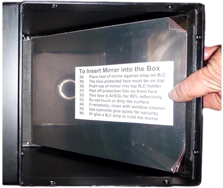
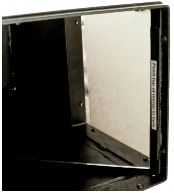
Installing the front-surfaced mirror
Focussing the Lens
and scintillator afterglow can be seen for some minutes after exposure to light
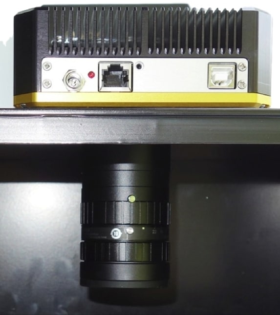
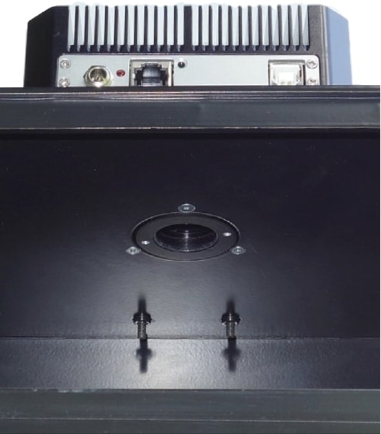 The CCD unit can be removed after first unscrewing the lens (left) to reveal three M3 bolts (right), which can then be unscrewed. There is no seal between the CCD unit and the box, and no adjustments, so the CCD unit can be easily replaced.
Do not touch the exposed surfaces of the CCD or lens, the front of which is protected by a UV filter.
The CCD unit can be removed after first unscrewing the lens (left) to reveal three M3 bolts (right), which can then be unscrewed. There is no seal between the CCD unit and the box, and no adjustments, so the CCD unit can be easily replaced.
Do not touch the exposed surfaces of the CCD or lens, the front of which is protected by a UV filter.
Installing a Newport Turntable for Tomography
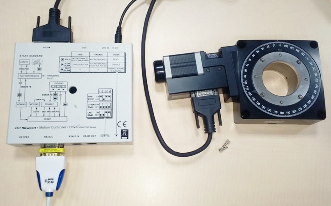
We recommend the Newport Micro-Controle URS turntables which start at ~€2500, together with the SMC100PP motor controller (~€650) with the SMC-PS80 power supply (~€93) and SMC-USB interface(~€63). The URS150BPP is usually sufficient, but for high loads, the RV120BPP can be used. These turntables use stepper motors for precise relative positioning without encoders.
You can use an SMC-RC manual remote control and display to rotate the turntable for alignment, and you may need an M-SK-4MA M4 screw kit to assemble the optional mechanical components such as a manual 9204-M Z-elevator, and X-Y translations M-423 with SM-25 Vernier Micrometers.
Mounting the sample base plate and Z,X,Y stages
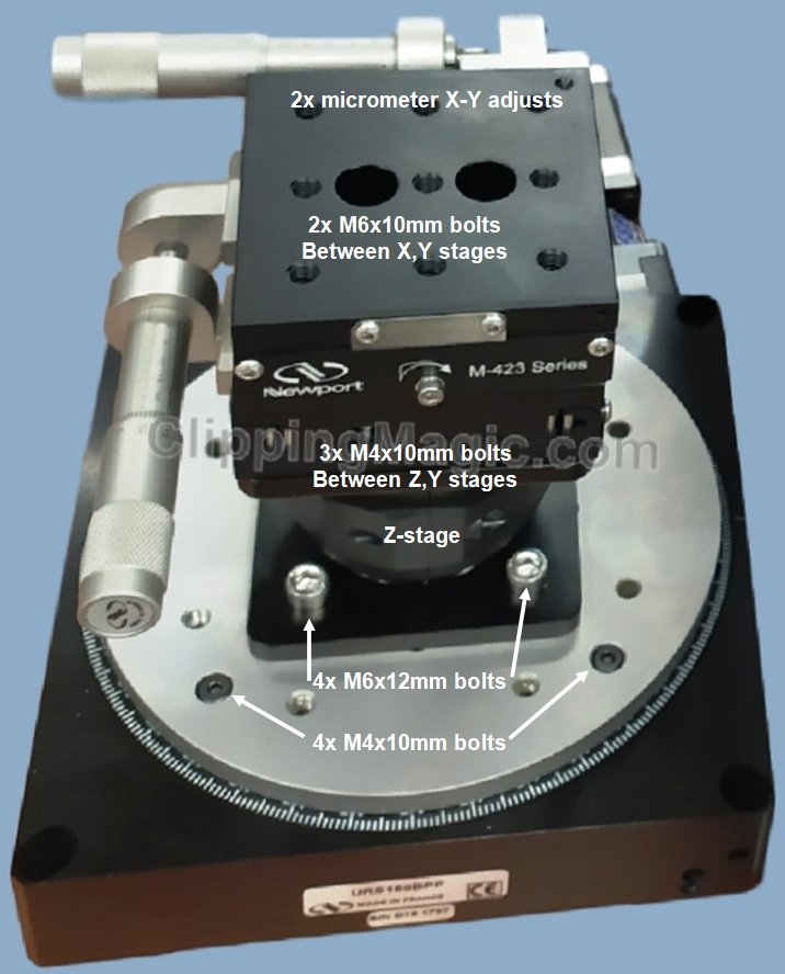 The Newport URS150BPP turntable is shown with its M-URS150TP top plate plus a manual 9204-M Z-elevator and M-423 X-Y translations with SM-25 Micrometers.
The mounting plate is bolted to the turntable using 4x M4x10mm hex bolts. then the Z-stage is bolted on top using 4x M6x12mm bolts. The X-Y stages are bolted on top using M4x10mm bolts with washers. Displace the top of each stage to obtain access to these bolts via the two large holes in the top of the stage. Instructions for mounting the micrometers are provided with the stages, with video instructions for stacking stages and swapping micrometer orientation.
You will probably want to change the +-165o hardware limits on turntable rotation.
The Controller Software & linking to Camera Software
C:\commands.bat | Plink -v -serial COM4 -sercfg 57600,8,n,1,N
Plink opens COM4 and configures it as required for the controller
echo 1PR0.5
timeout /t 1 /nobreak >nul 2>&1
taskkill /f /IM Plink.exe
exit
Command 1PR0.5 steps motor 1 to Position Relative 0.5o, wait 1s, then kill Plink & exit
NeutronOptics Fast Imaging Camera Specifications
Installing the Driver and Artemis Capture software
- Click the Windows "Start" button and open "Devices and Printers"
- Double-click the "Unknown Device", select "Hardware" then "Properties"
- Click "Change Settings" under the "General" tab
- Click "Update Driver" under the new "General" tab
- Choose "Browse for Drivers" on the Product Software CD
- Select the 32-bit or 64-bit driver from the drivers folder
- Click "OK" then "Next" then accept and install the camera driver
ArtemisCapture with the High Resolution Camera
Launch ArtemisCapture to display the image and controls. The "File" menu is used to save the last image, the "Camera" menu connects the camera if it is not done automatically, and the "Colour" menu should be set to "Raw". The icons under the menus launch a single exposure or continuous loop exposures. The three remaining icons open the Exposure, Display and Cooler tabs. IMPORTANT: Zoom out to see the green outline of the full CCD.
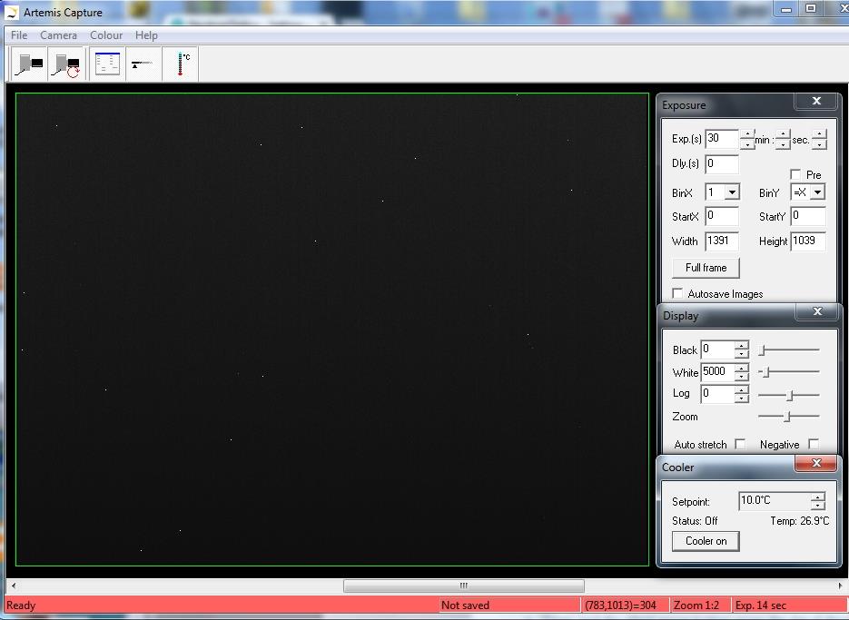
Click the image to enlarge it. The white dots are noise for a 30s un-cooled exposure.
Typically you would set the exposure time and click "loop" with Display "Auto stretch" on.
On the "Exposure" tab: (to speed up downloads e.g. when focussing with light)
• Set the exposure time (s) with BinX=4 and BinY=X for 4x4 binning
• A delay Dly (s) between exposures in loop mode can be set
• Check the "Pre" box to reduce the time for noise correction
• Do NOT check the "Pre" box for imaging; longer exposures will show noise spots
.
• Select StartX, StartY, Width, Height as 750, 750, 500, 500 to reduce readout time
• Use "loop" exposures of ~0.05s, which are sufficient for light (but not neutrons)
On the "Display" tab:
• Check the "Auto stretch" option to select the best 8-bits out of the 16-bits.
Note: scintillator afterglow may be seen for some minutes after exposure to light.
• "Zoom" (or the central mouse button) zooms the display window
On the "Cooler" tab:
• Set the temperature to -20oC to reduce noise when collecting neutron images.
• If the CCD is cold, click "Warm up" and wait a few minutes before disconnecting.
If the Artemis Capture window does not open, unplug/replug the power supply to reset.
Hints on getting Optimal Performance
- If the image is completely black, reduce the exposure to avoid saturation.
- The exposure time depends of course on the intensity of your beam
- 2x2 binning will give x4 the intensity and faster readout, but halve resolution
- You can also speed up readout by limiting it to a "sub-frame" of the full image
- The "Display" panel controls what you see, but has no effect on what you collect
- "Zoom" (and the wheel mouse button) zooms the size of the image display
- "Auto Stretch" compresses the 16-bit range of intensities to 8-bits for display
- But usually you will want to select the black and white display limits manually
- Image display is for guidance. Open the image with ImageJ for measurement
- The CCD can be cooled to reduce noisy pixels. You can also use ImageJ filters
- Fogging may occur if you cool below 0>C (the CCD chamber contains a desiccant)
- The desiccant can be replaced by removing the large screw on the camera shaft


Cooling becomes particularly important for very long exposures. The images above show a 300s exposure at ambient temperature (22C) (above left) compared to the same exposure after cooling to -6C (above right); only a few isolated hot pixels remain after cooling, and these can easily be removed with the ImageJ Despeckle filter. (Click images to enlarge).
For high quality images, do NOT check the "Pre" box for fast readout, and do NOT bin. Both will emphasise and smear out hot pixels, and make them more difficult to filter.
If you measure ONLY background, the display software will also emphasise hot pixels.
![]()
Occasional Problems with Camera Operation
- Be patient. Wait for ArtemisCapture to load and detect the camera
- ArtemisCapture may already be running. Unplug/replug the camera USB
- Check there is an ArtemisCCD device in Control_Panel/Devices_and_Printers
- Check that the services ArtemisHscService, ArtemisHSCServiceMonitor and AtikCamera Register are running in the Services tab of the Task Manager
- Try deleting the ArtemisCapture.ini file from the C:\Windows folder to reset it
- Try a different USB port, waiting for the driver to be found and re-installed
- Shut down the computer, remove the power cable for a few seconds, then reboot
- If all else fails, try using a different computer
- Change the 12V 2A camera power supply (standard 2.5/2.1 mm outer/inner plug)
- Before you attempt to dis-assemble the camera or CCD unit, please email me !
- The center of the image doesn't correspond to the centre of the window
because the CCD chip is not centred to better than 0.5mm in its housing
Image Treatment with ImageJ
ImageJ is recommended for image analysis. ImageJ will open the 16-bit raw FITS files produced by Artemis Capture, remove noise, modify contrast and other properties, and save them in various formats. More importantly, it will allow you to measure intensity profiles and display your data in ways that will make it more meaningful. For example:
- The ImageJ "Process/noise/despeckle" filter will remove isolated hot white pixels
- To correct for barrel distortion install the ImageJ Barrel Distortion macro tool
A complete ImageJ installation is included on the NeutronOptics software CD under "Extras". Copy the ImageJ folder to your C: disk & launch ImageJ to set defaults and update ImageJ.
Tomography
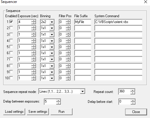
For tomography you can collect a series of images, calling a script to rotate the sample after each image by using camera/sequencer. In this example we take 360 2x2 binned exposures of 4s (with no filter), writing individual files to "MyFile???.FITS" then executing script "orient.vbs" and waiting 5 seconds before starting the next exposure. You can substitute any type of script or application for "orient.vbs". See also ImageJ-for-ASCOM.
For tomography, a precision sample turntable is needed to rotate the sample in increments of eg 0.5 degree between images. For samples of up to 30 Kg, we recommend the Newport Micro-Controle URS turntables which start at ~€2500, together with the SMC100PP motor controller (~€650) and SMC-PS80 power supply (~€93) and SMC-USB USB interface(~€63). For high loads, the RV120BPP, a smaller version of the RV350BPP used at ILL, is recommended. The Newport turntable is controlled by COM port scripts eg using PuTTY's Plink command. A system file orient.bat is used to pass a file commands.bat to the turntable eg 1PR0.5
orient.bat: C:\commands.bat | Plink -v -serial COM4 -sercfg 57600,8,n,1,N
commands.bat: echo 1PR0.5 , timeout /t 1 , taskkill /f /IM Plink.exe , exit
Plink opens port COM4 and pipes commands such as 1PR0.5 to 1 Position Relative 0.5o.
waiting 1s before killing Plink, which will be restarted after the next camera acquisition.
But first open the SMC100 Software, click “Initialize” so the controller light turns blue.
All our cameras aquire images in 16-bit greyscale FITS format, from which ImageJ can create TIFF stacks of sequential projections. Applications such as MATLAB or OCTOPUS and free applications such as MuhRec, can be used for tomographic reconstruction of a stack of sections from a stack of projections. The ImageJ 3D Viewer can display stacks as texture-based volume renderings, surfaces or orthoslices. But first read one of the free on-line books such as Principles of Computerized Tomographic Imaging and The Scientist Digital Signal Processing.
ImageJ for ASCOM is also suitable for tomography, Laue diffraction and very low-flux acquisitions. The acquired images are opened directly in ImageJ, and you can easily modify the interface by extending the ImageJ scripts. At the end of each image acquisition, a Windows routine Orient.vbs is launched (if it exists) to eventually re-orient the sample. You can simultaneously acquire images from dual-CCD Laue cameras and stitch them together.
LabView and Artemis Software Developement Kit (SDK)
The camera can also be controlled using LabView, National Instruments' graphical programming environment for instrument control. You can download a free time-limited version if you want to control our camera together with other instruments. Excellent LabView on-line tutorials are available, as are a set of simple LabView (*.vi) files to control the high resolution camera. Note that you also need the LabView Vision Developement Module, and you can download a free evaluation version.
We cannot provide support for LabView, for which you must rely on National Instruments or the NI user group, which has posted example files for Artemis cameras. One of our clients used a simple LabView application to control his sample turntable, and then used the ArtemisCapture/sequencer to call that Labview routine after each image acquisition.
The Artemis SDK Software Developement Kit contains C++ support and example files to allow you to develope your own camera acquisition code.
Camera Control and Image Acquisition with Nebulosity
You can also use the PHD application for simple real-time image capture with the Hi-res camera (without cooling), or the Nebulosity3 application, with either the Atik/Artemis driver or the ASCOM driver. These applications are also available for macintosh systems.Sequential Image Stacking with Artemis Infinity
The Artemis Infinity software, which works for all Atik high resolution cameras, can be installed with Atik core software; it can collect a series of short exposures, adding them together in real time. You can then see how a longer exposure is progressing eg with the 1-CCD Laue camera. Click the images to enlarge them
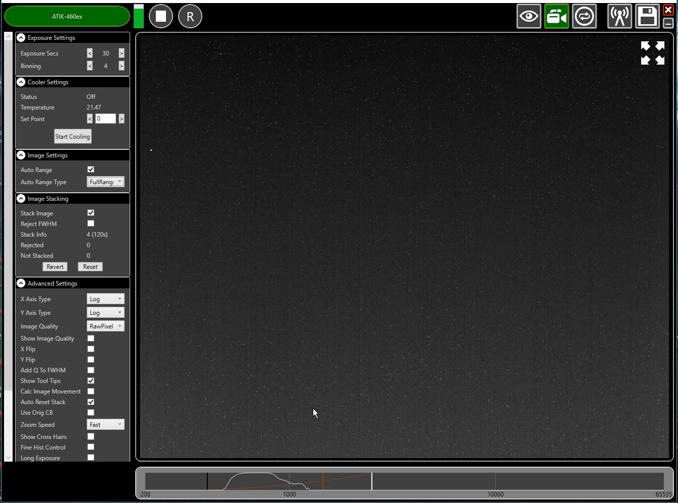
- Double-click the top bar to expand/contract the window.
- If connected, the camera name is shown in green
- Set the exposure time and binning (to 30s and x4 for the Laue camera).
- Advanced Settings: Uncheck "Calc.Image Movement" & Check “Long Exposures”
- Select the "video camera" icon on the top right to enable stacking
- In the "Image Stacking" dialogue that appears on the left Uncheck "Reject FWHM"
- The green triangle starts exposures, turning into a white square to stop exposures
- The "Stack Info" shows the number of images averaged (and the total exposure)
- The bar at the bottom controls the image display range
- Check "Auto Range" in the "Image Settings" and eg "FullRangeMinus"
- Otherwise, drag the vertical markers to bracket the display intensity range
- Noise is evident because we didn't cool. Set Temperature to 5C in "Cooler Settings"
- If the camera is being cooled, click "Warm Up" before disconnecting power
Slightly different manuals are available for our high resolution CCDs our hot neutron camera our VS60 high resolution camera.our FS60 high resolution camera. our 1CCD Laue camera and our advanced imaging camera.