Read also the old CLIP manual with the more recent ILL CLIP Tutorial.
See also the old OrientExpress manual with the Tutorial below.
CLIP for Simulating a standard Si [111] Laue Pattern
CLIP
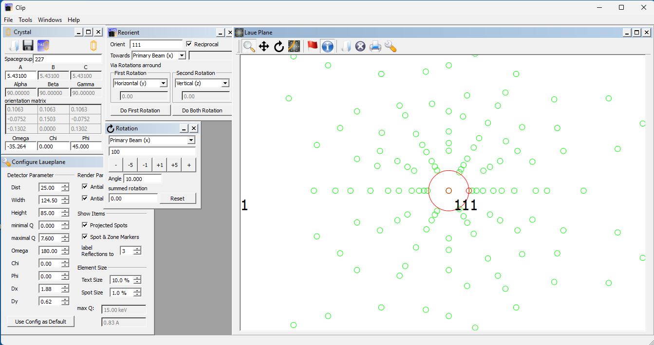
(Cologne Laue Indexation Program) is a Windows application written by Olaf Schumann that may be used for Laue indexing and crystal orientation. Open CLIP, drag the window to enlarge it, and then drag the Laue Plane window to uncover the Crystal window. (If closed, these windows can be opened with the File/New Crystal and File/New Laue Orientation menus). Enter the Space Group (number or symbol) and lattice constants (A,B,C) with angles (Alpha, Beta, Gamma), which will be constrained by the Space Group. Here the group is 227 and the cubic cell 5.431 Ǻ. Click the Crystal disk icon to save the cell information to a file *.cell.Click the Laue/Spanner icon to configure the Laue Plane by entering the Distance of the crystal from the camera window, with the Width and Height of the window. We have entered 25 mm though more commonly it would be ~40 mm. The 3:2 NeutronOptics 1-CMOS detector sees a window of ~124.5x85 mm. The minimal and maximal Q (0, 7.6) define the x-ray energy band as up to 15 keV. These numbers only determine the number of visible Laue spots. Most importantly the angle Omega between the incident and reflected beam is 180 for Back Reflection (or 0 for Transmission Laue)). (Chi, Phi) define the orientation around the beam, and (Dx, Dy) the displacement of the beam centre. Click Use Orientation by Default to save it.
The default orientation [100] can be changed by opening the Tools/Reorientation menu, and entering an Orient vector, here [111] towards the Primary Beam. Clicking Do Both Rotations will perform both an Omega and a Phi rotation to align the chosen vector along the beam. Tools/Rotation will perform minor rotations if required.
Try simulating any Laue pattern this way.
![]()
Defining Zones and Orienting a standard Laue Pattern
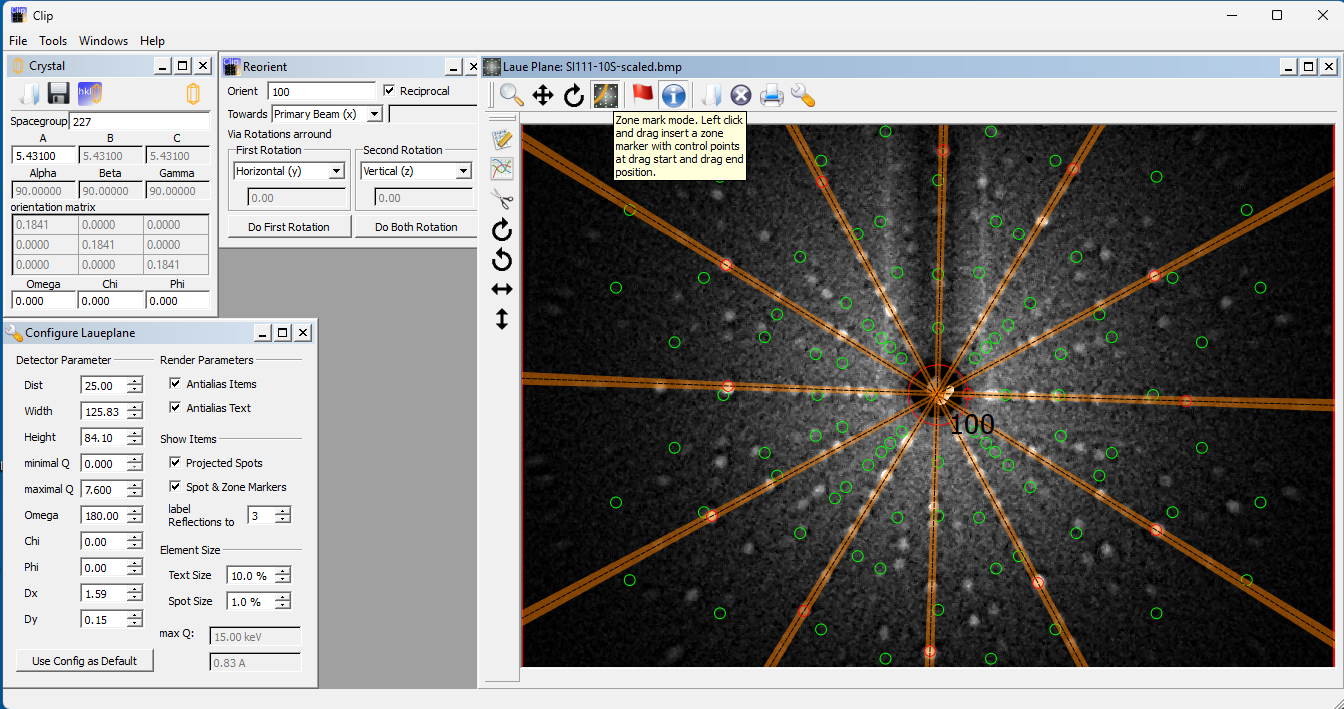
Click the 4th last book icon in the Laue Plane window to open a Laue Image file, in this case Si111. We have reset the calculated Laue pattern back to the default [100] orientation, but it doesn’t matter what the initial orientation is, because we will determine it by identifying and matching Zone lines. Click the small red circle and move it to the centre of the pattern (the intersection of the rows of spots, not necessarily the bright central beam spot). Click the small circle on the large red circle to adjust the excluded central zone.Now click the Zone Mark mode, the 4th icon in the Laue Plane window. Click on a Laue spot and, holding down the mouse button, drag and click on a second Laue spot on the same arc. In this high symmetry pattern, the arcs are straight lines through the centre, but in general they will be hyperbolas for back-scattering (or ellipses for transmission). In this way, define a number of Zone arcs.
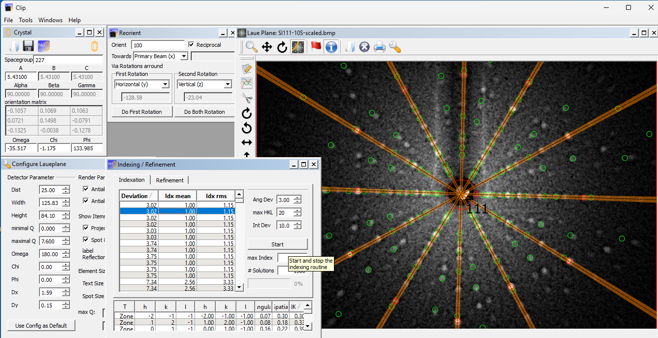
Click the 3rd HKL icon in the CLIP Crystal menu to open the Indexing/Refinement window. In that window, click Start and then click Stop. Indexing is very fast and multiple solutions will be listed with increasing Deviation, with Mean and RMS deviations listed. Click on one of the best fits to display the calculated Laue spots and the corresponding axis. In this case, the best fits all correspond to an equivalent [1,1,1] or [1,1,-1] etc., as expected.
Note that we assumed an arbitrary distance of 25 mm for the distance of the crystal from the camera window. This distance, along with the precise dimensions of the camera window, will determine the scale of the pattern and the location of the individual spots. Yet even without these geometric parameters we were able to determine the crystal alignment simply from the zone lines.
The precise dimensions of the window could be determined by placing fine lead markers on it. Eventually, small optical distortions, could be corrected using a larger absorbing grid with a barrel distortion routine in imageJ (https://neutronoptics.com/downloads/Barrel%20Distortion.txt)
To obtain a better correspondence between calculated and observed Laue spots, first remove the zone lines by selecting the Zone tool and right-clicking on them. Use the I-tool to click on the individual spots to identify them or open the CLIP/Tools/ReflexInfo and move the mouse over the pattern to identify spots and their orientation relative to the beam and axes.
Refining the Orientation of a standard Laue Pattern
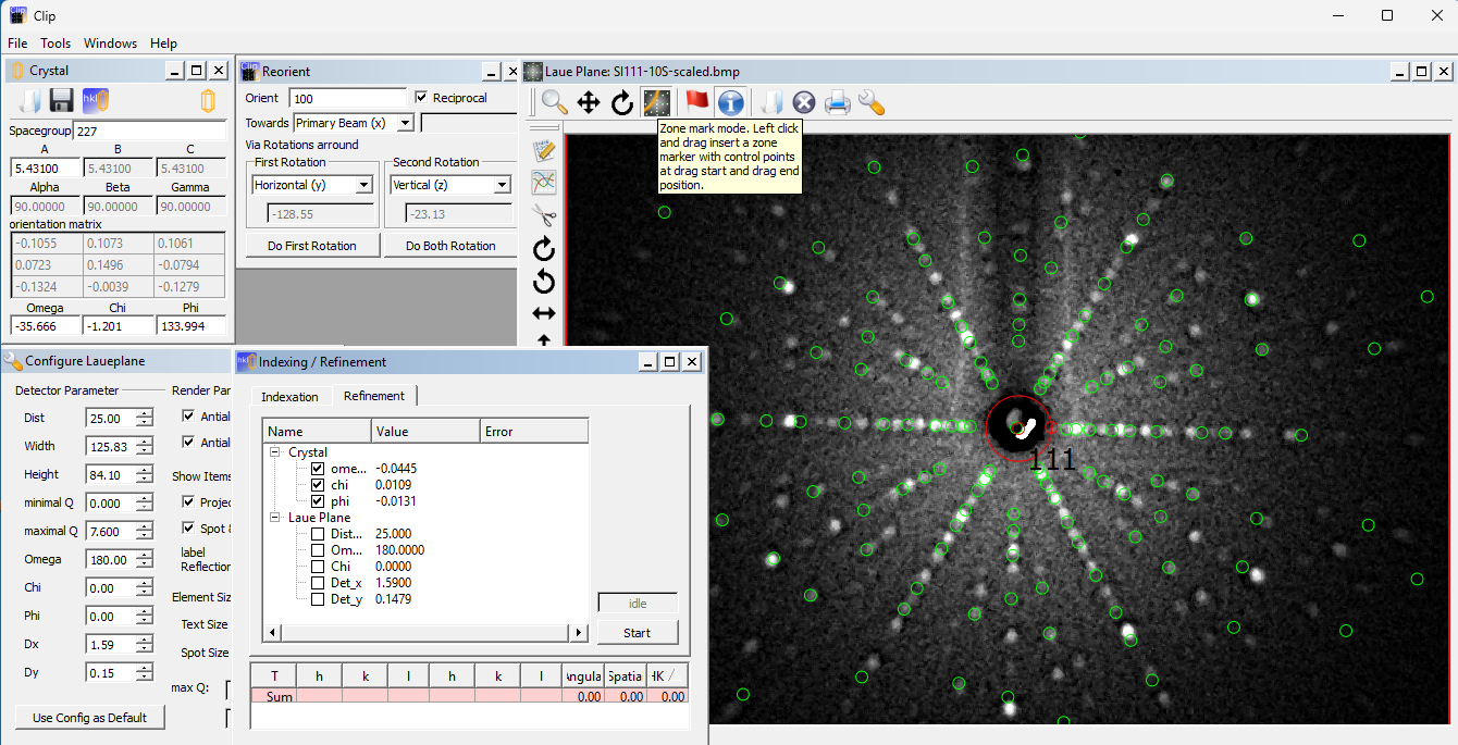
CLIP has an option for refining the crystal orientation and distance to the camera, but that may not be very useful if the deviations are mainly due to errors in camera geometry. Read the CLIP manual and ILL Tutorial for further details.![]()
Alternative OrientExpress program for Laue Indexing
 OrientExpress is a Windows application for automatic Laue indexing, developed by Jean Laugier,
with help from Bernard Bochu at LMGP Grenoble, and Alain Filhol at the Institut Laue-Langevin (ILL). It can be
downloaded with example files.
OrientExpress is a Windows application for automatic Laue indexing, developed by Jean Laugier,
with help from Bernard Bochu at LMGP Grenoble, and Alain Filhol at the Institut Laue-Langevin (ILL). It can be
downloaded with example files.
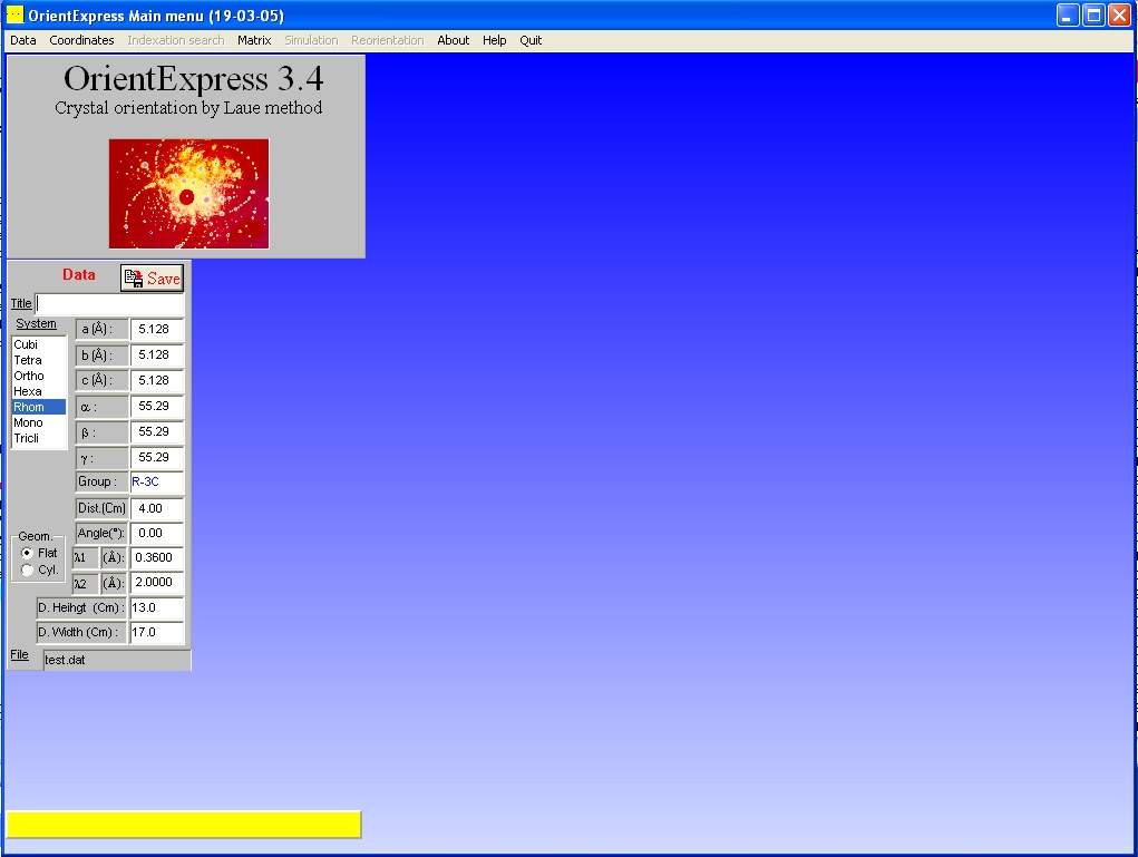
Under the Data/File menu select "EXAMP1.DAT", which contains
lattice dimensions for a ruby test crystal (Al2O3) together with the characteristics
of the camera (distance to crystal, angle between the beam and the camera normal,
wavelength range, and camera screen dimensions). Note that this is transmission Laue data, so the angle is 0o;
it would be 180o for backreflection Laue. Al2O3 is given on hexagonal axes, but the
programme can convert to rhombohedral axes, for which indexing is easier. You can look up lattice
dimensions on the Inorganic Crystal Structure Database (ICSD).
Measuring the Laue peak coordinates
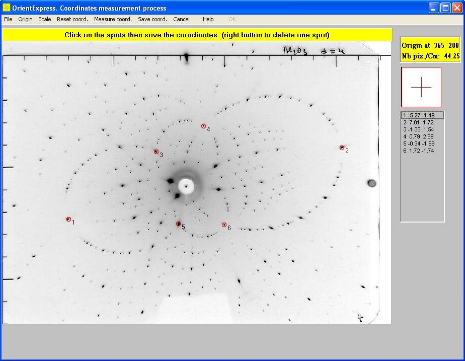 Under the Coordinates/Image menu select "examp1b.jpg" or a Laue pattern you saved from your camera.
Select the Origin/Circle menu from the new "Laue" window that opens. Click and drag the red circle to define
the beam axis of the Laue pattern (not always coincident with the centre of the beam hole) then click "OK". Select the Scale/Enter menu and enter the number of pixels/cm; 44.25 for the
examples or 50 for
the 150x120mm NeutronOptics Watec camera. Check these numbers at the top left of the screen. Now click "Measure coord."
and click on up to 10 spots (right click to remove a spot). It is best to select only 5-6 spots that are at the
intersections of arcs of spots (zonal lines) which usually have small h,k,l indices. Finally, click "Save coord." to a file.
Note that the laue spots fall on ellipses, indicative of transmission Laue geometry; in backscattering geometry the spots
fall on hyperbolas, the intersection of the scattering cones with the detector plane.
Under the Coordinates/Image menu select "examp1b.jpg" or a Laue pattern you saved from your camera.
Select the Origin/Circle menu from the new "Laue" window that opens. Click and drag the red circle to define
the beam axis of the Laue pattern (not always coincident with the centre of the beam hole) then click "OK". Select the Scale/Enter menu and enter the number of pixels/cm; 44.25 for the
examples or 50 for
the 150x120mm NeutronOptics Watec camera. Check these numbers at the top left of the screen. Now click "Measure coord."
and click on up to 10 spots (right click to remove a spot). It is best to select only 5-6 spots that are at the
intersections of arcs of spots (zonal lines) which usually have small h,k,l indices. Finally, click "Save coord." to a file.
Note that the laue spots fall on ellipses, indicative of transmission Laue geometry; in backscattering geometry the spots
fall on hyperbolas, the intersection of the scattering cones with the detector plane.
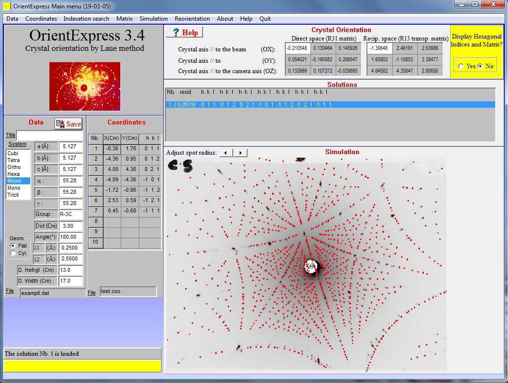
Indexing the Laue pattern & crystal orientation
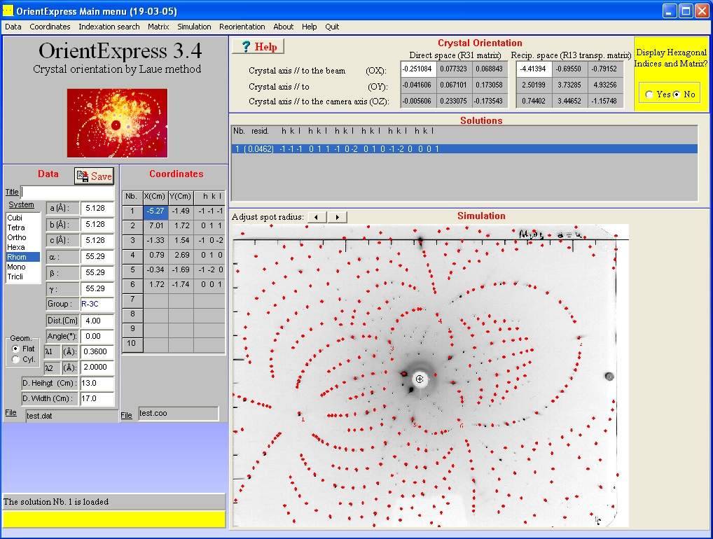 On the OrientExpress main menu, click "Indexation search" and simply click "OK" in the dialogue that opens.
If indexing succeeds, a red Laue pattern will be super-imposed on your measured image corresponding to one of
possibly several solutions (click on the different solutions if there are several). A correct solution will
reproduce the observed spots (plus a lot more) and most importantly, the intersecting arcs of spots. If there
is no good solution, check the centering, scale and cell parameters or select fewer Laue spots only on arc intersections.
The menu Coordinates/Modification modifies the coordinate list or centre/scale image constants.
On the OrientExpress main menu, click "Indexation search" and simply click "OK" in the dialogue that opens.
If indexing succeeds, a red Laue pattern will be super-imposed on your measured image corresponding to one of
possibly several solutions (click on the different solutions if there are several). A correct solution will
reproduce the observed spots (plus a lot more) and most importantly, the intersecting arcs of spots. If there
is no good solution, check the centering, scale and cell parameters or select fewer Laue spots only on arc intersections.
The menu Coordinates/Modification modifies the coordinate list or centre/scale image constants.
Refining the fit to the Laue pattern & orientation
On the OrientExpress main menu, select Matrix/Refinement and "No additional coordinates" then click "Refine". Try refining again after adding more Laue spots. The resulting file "Report.txt" will list the (h,k,l) of all the Laue spots used for the refinement as well as their position on the pattern, their deviation from the calculated pattern, and the refined distance between the camera and crystal.Rotating the Laue pattern & simulation
On the OrientExpress main menu, select Simulation/Laue and then select the rotation axes under the Options of the simulation window. Dragging the mouse in this window will rotate the Laue pattern around the selected axes. You can also choose the Indexation option and click on Laue spots to identify them, increasing their size as necessary. Even if you can't index the pattern, you can simulate it given the Ox,Oy,Oz crystal orientation axes by entering these under the Matrix/Acquisition menu then using the Simulation/Laue/Options menu as above to adjust the crystal orientation.Steffen Weber has also programmed a simple interactive Laue pattern simulator in Java.
Re-orienting the crystal on new axes
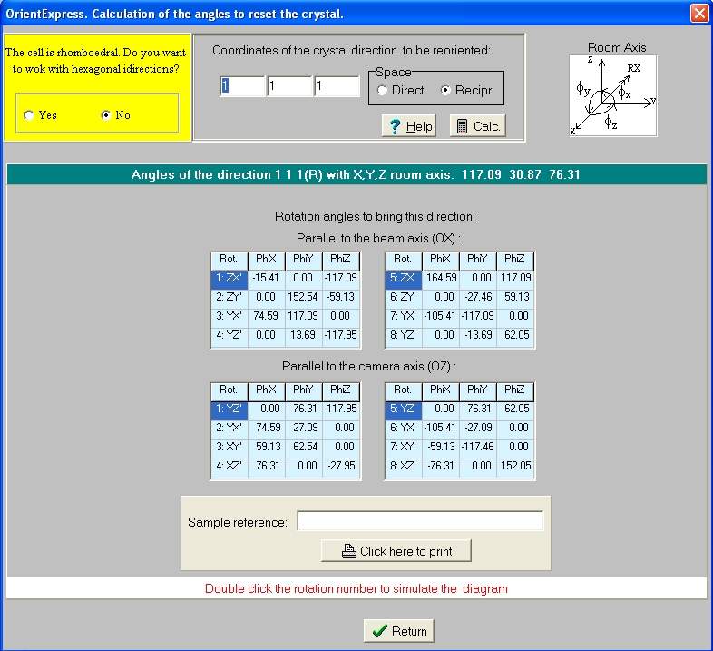 On the OrientExpress main menu, click "Reorientation" and enter the crystal orientation eg (1,1,1)
that you want either parallel to the beam axis OX, or parallel to the
vertical camera axis OZ, then click calculate. You will obtain a number of combinations of rotations
phiX, phiY, phyZ that will achieve that. Choose the solution most convenient for your goniometer.
On the OrientExpress main menu, click "Reorientation" and enter the crystal orientation eg (1,1,1)
that you want either parallel to the beam axis OX, or parallel to the
vertical camera axis OZ, then click calculate. You will obtain a number of combinations of rotations
phiX, phiY, phyZ that will achieve that. Choose the solution most convenient for your goniometer.
Finally you can click on one of these solutions to display the expected Laue diagram, and you can
check your new orientation by comparing that with a new measured diagram.
Indexing backscattered Laue patterns
For backscattered Laue patterns, the "Angle" in the data file becomes 180o as in the "examp6.dat" file. File "grolland.bmp" is a backscattered pattern from ruby where we have measured 7 spots (below left) which allows us to find a unique solution (below right).
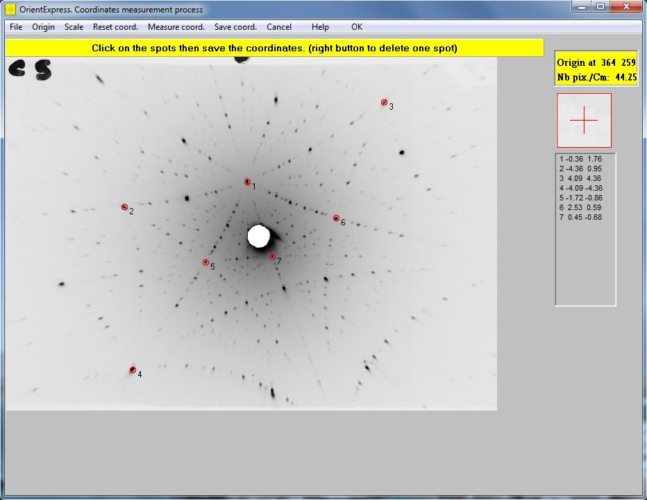
Note that we have chosen spots at the intersections of multiple arcs indicative of low order reflections in symmetry directions. Try removing the last 3 spots; you will still find a solution. Try adding spots at the intersections of fewer arcs; a solution is more problematic. Use only a few low order reflections to find a solution, then refine it.
The Laue patterns shown here are the X-ray scattering examples provided with the OrientExpress software, not those obtained with our cameras.
For Windows-7, install OrientExpress in write-enabled directories, not "Program Files".
These brief instructions should be supplemented by the original OrientExpress manual.