Orienting Crystals with the 2-CCD Laue Camera
Note! We have recently developed simple, more efficient CMOS Laue Cameras.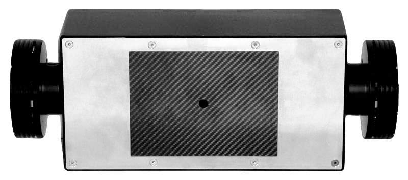
We have developed an inexpensive replacement for the old Polaroid Laue camera, based on the original Orient Express camera for neutron Laue diffraction. Like Orient Express it consists of a dual-CCD camera with real-time read-out. Large aperture lenses are used to image the scintillator onto the CCDs, which also have micro-lenses over each pixel. This camera is similar to the old Polaroid Laue camera, in being simple, efficient and low cost, but the image is available immediately for the determination of crystal orientation.
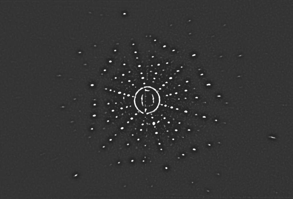
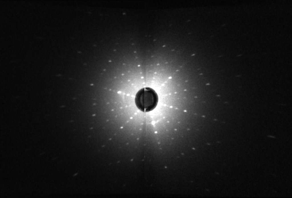
The NeutronOptics Laue Camera uses twin CCD units to increase efficiency, extend the image field, and avoid the shadow from the central collimator. The separate images are automatically stitched together using free ImageJ software to produce a single 160x120mm image after correcting each for its relative position, angle and lens aberrations. Below is a highly compressed JPEG image of more detailed raw Laue data obtained in 300 seconds with 35kV/50mA Cu-anode x-rays backscattered 30 mm from strongly absorbing Pt(111). Data courtesy of Nakkiran Arulmozhi, in Professor Gregory Jerkiewicz's laboratory, the Chemistry Dept., Queen's University, Ontario Canada. For further details see their published papers.
Note! We have recently developed simple, more efficient CMOS Laue Cameras.
Touch the mouse on the image to apply imageJ's band-pass filter to emphasise the peaks. A central collimator (not shown) collects the beam transmitted through the crystal in forward scattering, or allows the incident beam to pass through the camera before being reflected by the crystal in backscattering. In either case, many Bragg spots are obtained from the different wavelengths in the white beam. Backscattering is used when the crystal is too absorbing for forward scattering, though intensities are much lower.
Our Laue camera can be supplied with scintillators, windows and collimators suitable for either neutrons or X-rays.
The photo shows an x-ray camera with twin
high resolution CCDs. The 160x120mm carbon fibre window
takes a collimator tube through its centre.
Transmission of the carbon window is estimated to be >70% even for CuKα X-rays (8 KeV).
The design is a compromise between low cost and high efficiency. The efficiency could be doubled for the same cost with
a smaller 120x90mm window in a 250x120x60mm box,
or for almost twice the cost with larger CCDs and lenses in the same 300x150x100mm box.
A less expensive 120x100mm Laue camera with only one large 1" CCD can also be supplied.
![]()
Setting up the Laue Camera
First read the instructions for standard NeutronOptics video cameras, or the instructions for the high resolution CCD Option. If the Laue camera has two CCD units, you have two power supplies and two USB connections, preferably using different USB hubs.Mount the camera as close to the source as possible using the 4mm bolt holes on the back; minor adjustments to position and orientation should be provided. Before inserting the collimator tube into the camera, check that it fits the source exit and allows no x-ray leakage. Insert the machined end first from the back of the camera, screwing gently until, with the x2 CCD camera, it protrudes from the front window. Do not apply lateral force, since the collimator traverses a hole between two mirrors.
The camera and collimator must be precisely aligned, and the source voltage and current set for maximum x-ray intensity through the collimator.
 Our mini i-Cam camera could be used to maximise the beam and position the sample, otherwise use the Laue camera itself to image transmission through the collimator.
If you have a single CCD camera, just follow the instructions for the high resolution CCD and then skip to Indexing
Typical exposure times for backscattered Laue are ~300 seconds. But first try a shorter exposure with
no beam to check that everything is working - you should see background noise. Then try forward
scattered Laue, where exposure times are much shorter. (Remove the collimator plug-ins if fitted so that the
waste beam passes through).
![]()
Using ImageJ for a Laue Camera with Hi-res CCDs
Start exposing both CCDs simultaneously. You may need to re-read the images after swapping the USB cables
so that the acquisition software adds the images from the two CCDs in the correct order.
Facing the front of the camera, CCD#1 is on the left, and should also be on the left in the display.
Over-expose CCD#1 to check this order.
This section assumes that you have hi-res CCDs.
See the next section for video CCDs.
First install the drivers and software for the Atik high resolution CCDs.
You can check that they are working individually by using "Artemis Capture", but you will need
ImageJ for ASCOM to capture both cameras simultaneously and stitch together their images.
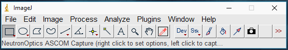
Install the ImageJ for ASCOM environment. Click the >> icon in the ImageJ toolbar and select the ASCap capture tool (camera icon).
![]()
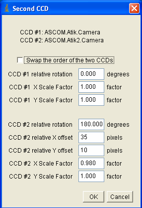
Right-click the resulting camera icon to choose two different "Atik" CCDs by clicking the ASCOM "Properties" dialogue. Make sure you attach different ART-TS14 CCDs to "Atik Camera" and "Atik Camera 2". Check that you have the latest Atik/Artemis ASCOM driver.
The "Second CCD" box allows you to swap the CCDs if necessary and eventually to set their relative parameters. These will be affixed to the actual camera.
CCD#1 must be on the left facing the camera screen and the computer screen. You may need to over-expose CCD#1 or swap USB cables to check the order.
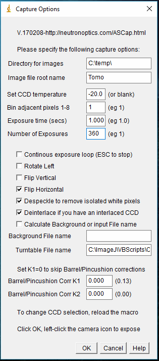
The "Capture Options" box then allows you to set the directory to save images, the image file root name and CCD temperature. You can bin adjacent pixels (2x2) to increase intensity, and set a necessarily long exposure time for x-ray backscattering.
"Despeckle" removes isolated noise pixels, and "Calculate Backround" removes diffuse background. Alternatively you can measure a "dark-field" image and subtract that file.
To enable optional lens corrections, install the SplineDeformationGenerator. (see the documentation). Double-click the mySplineDeformationGenerator.zip file and drag the mySplineDeformationGenerator folder to the C:\ImageJ\plugins directory.
SplineDeformationGenerator will appear in the Plugins menu when you restart ImageJ. It will only be used if parameter K1 is set.
Click OK then left click the camera icon to start exposing both CCDs simultaneosly.
To re-expose with the same parameters, left-click the camera icon, or right-click it to change the exposure parameters.
To obtain the "Second CCD" box, hold down the "Alt" key while right-clicking. Or hold down the "Alt" key immediately the composite image appears. This can be used to adjust the CCD#2 camera offsets.
You can even re-compose the composite image from existing individual images and adjust camera offsets
by holding down "Alt" while left-clicking the camera icon.
![]()
If you have problems with collecting images...
- Try a 1s exposure to check that it works before starting a long exposure
- Check that you have the latest versions of ASCap.txt and ASCap.vbs
- Use a Windows-7 or -XP computer with at least 2GByte of memory
- Close other aplications and windows that may use memory
- Try unplugging and re-plugging the USB cable
- Try re-booting your computer :-)
- Check the files that are created in your image directory
- Note that the lens distortion correction is not perfect far from the center
- If ever you need to recalibrate parameters (you should not need to do that) replace the window & scintillator with graph paper and use very short exposures
Using ImageJ for a Laue Camera with video CCDs
This section assumes that you have video CCDs. See the previous section for hi-res CCDs.
Download the ImageJ AMCap macro to your \ImageJ\macros\toolsets folder. Click the >> icon in the ImageJ toolbar and select the AMCap capture tool (camera icon).
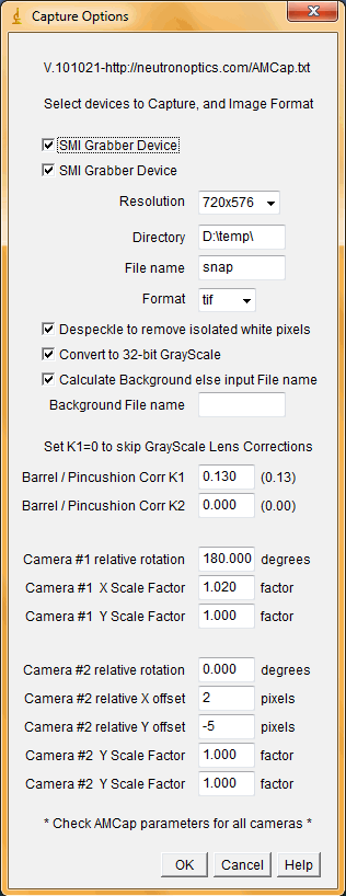
Right-click the resulting camera icon to bring up the options dialogue opposite. Depending on installed software and versions, fewer options may be shown.
Select the cameras to capture eg "USB 2861 Device" or "SMI Grabber Device", resolution, image directory, file name and format. "Despeckle" removes isolated noise pixels,
"32-bit grayscale" converts the 8-bit images to 32-bit, and "Calculate Backround" removes diffuse bright patches due to amplifier glow from the image corners. Alternatively you can measure a "dark-field" image and subtract that file.
Set the pincushion lens corrections K1, K2, camera rotation and X,Y scale factors. When there is a second camera, set its rotation, X,Y offsets and X,Y scale factors.
These parameters will be supplied for each camera; if ever you need to re-determine them, you can use a pinhole calibration screen in place of the scintillator plate.
Click OK then press the red buttons on the controllers to start exposing, then press these buttons again to stop integration and store the images (red lights come on). These images remain stored and you can read them out at any time.
Left-click the camera icon to treat the images, watching progress in the tool bar. Then re-read the AMCap instructions !
If necessary, click the camera icon again to re-treat the images stored in the cameras.
![]()
Indexing and orienting the Laue pattern
You may first want to use ImageJ's "Process/Noise/Despeckle" to filter out electronic noise and perhaps "Process/FFT/Bandpass filter" to emphasise the peaks, before using imageJ to convert to the various formats used for indexing. A number of Laue indexing applications are freely available. The Cologne Laue Indexing Program (CLIP) is one of the best, along with the QLaue Indexing Program. Older applications such as OrientExpress and the ambitious new ESMERALDA Laue suite might also be tried. If you just want to simulate a Laue pattern without installing any software, try the ILL's JAVA Laue simulator.And don't miss the video of the astonishing power of CYCLOPS, the 4π Laue camera !